FAQs for Fabrication Partners
Tri‑Power offers Smart Power motors in an 0.8 Nm pull‑wand motor for small shades, 1.1 Nm, 3 Nm and 10 Nm ratings for interior shades, and AC motors in 20 Nm and 50 Nm ratings for exterior applications.
The 1.1 Nm motor suits lightweight roller shades and is comparable to a 1 Nm battery motor that can lift roughly 5–7 kg (11–15 lb) on a 38–50 mm tube. 3 Nm motors are intended for medium‑weight shades; 10 Nm motors handle larger interior shades. 20 Nm and 50 Nm AC motors drive large or heavy exterior shades. Actual lift capacity depends on shade design, tube diameter and fabric weight; consult our engineering team for project‑specific recommendations.
Yes. Smart Power motors can be connected to a 20–24 V DC power panel using only
the black and red wires. Each motor should have at least 0.5 A available.
When wired directly, do not connect the Smart Power Hub. The hub is used only for
Smart Power bus installations.
Smart Power motors must be powered by the Tri‑Power 65 W power supply when
used with the Smart Power Hub. Use only Tri‑Power‑branded USB‑C motor cables to
ensure proper communication.
While charging the motor’s internal battery, any standard USB‑C cable and 5 V charger
can be used. *Charge time overnight
Yes. The lead from the motor head to the splice is a proprietary Smart Power cable supplied in 6‑ft (1.8 m) and 12‑ft (3.6 m) lengths. When shortening a run, trim only the three‑conductor end and do not cut or remove the USB‑C plug, as it is required for Smart Power functionality. Always use genuine Tri‑Power motor cables and connectors. If you need custom lengths or have installation questions, please consult our support team.
Yes. Tri‑Power motors can be integrated with most third‑party automation platforms including Control4, Josh AI, Google Home and others—via the Bond Bridge or Bond Bridge Pro devices. See bondhome.io for details on compatible bridges.
No. Three‑way bus connectors simplify installation, but any suitable wire connector
(e.g. wire nuts) may be used. When not using the Tri‑Power connector, reinforce the
splice with electrical tape for security.
No. Tri‑Power exterior motors are AC‑powered and must be connected to 120 V.
They do not connect to the Smart Power Hub.
Smart Power motors use a 3‑wire 18/3 cable that can be run up to 500 ft (152 m) per branch. We recommend a loop‑and‑splice method for bus connections; Tri‑Power three‑way connectors simplify the process but are not required. For runs up to 500 ft (152 m) from the hub or bus, use a shielded 18/3 cable. The Smart Power bus supports daisy‑chain, star, tree or hybrid wiring layouts; each bus port on the hub can support up to 500 ft of cumulative wiring.
FAQs for End‑User Support
If you are an owner or installer of Tri‑Power motors, this section explains common
programming and operation topics. Our virtual assistant Chris is available by phone at
802‑689‑1199; he can email you drawings, step‑by‑step instructions and programming
videos (approximately 5–6 in total) and provide guidance on special cases.
To pair a new remote: (1) Wake the motor by pressing its program (Prg) button; the
LED will blink. (2) On the remote, press the Prg button once to start pairing; the motor
will jog. (3) Press the Prg button again to confirm pairing; the motor jogs again.
Depending on your remote model, pairing sequences may vary. Please refer to the
programming video for your specific motor and remote.
Limit setting allows the motor to stop automatically at the top and bottom of the
window.
- Move the shade to the desired upper limit using the Up button, then press the Favorite
(Fav) and Up buttons together for 2 seconds; the motor will jog. - Move the shade to the desired lower limit using the Down button, then press the Fav
and Down buttons together for 2 seconds; the motor will jog again.
These actions save the upper and lower stopping points. Always set limits before using
favorite positions or automation.
Yes. If the shade travels opposite your remote buttons, you can reverse the direction.
If limits are set, press the Prg button on the motor, then press the Up and Down
buttons briefly on the remote; the motor will jog and reverse.
After reversing, re‑check limit positions and reset them if necessary.
If limits are not set, press and hold the Up and Down buttons simultaneously for
2 seconds; the motor will jog and change direction.
Yes. The lead from the motor head to the splice is a proprietary Smart Power cable supplied in 6‑ft (1.8 m) and 12‑ft (3.6 m) lengths. When shortening a run, trim only the three‑conductor end and do not cut or remove the USB‑C plug, as it is required for Smart Power functionality. Always use genuine Tri‑Power motor cables and connectors. If you need custom lengths or have installation questions, please consult our support team.
To enable one‑touch mode (tap‑to‑move) or constant‑touch mode (hold‑to‑move),
press the Prg button followed by the Stop button twice (Prg + Stop + Stop). The motor
will jog, and the LED colour will change to indicate the new mode.
Move the shade to the desired intermediate position, then press the Fav and Stop
buttons together for 2 seconds. The motor will jog, confirming the favorite position.
To use the favorite position, press the Fav button once. To clear it, repeat the Fav +
Stop sequence for 2 seconds.
Obstacle detection stops the motor when an object is encountered.
- To enable the obstacle detection mode, press Prg + Up + Stop. The motor’s LED will
flash blue. - To disable the mode, press Prg + Prg + Stop + Stop; the LED will flash orange.
By default, obstacle detection is enabled on most motors.
With obstacle detection enabled, you can select sensitivity levels 1–5.
Press Prg + Up + Up to cycle through sensitivity levels (the motor jogs and flashes to
indicate the current level). Level 1 is least sensitive; level 5 is most sensitive.
Alternatively, press Prg + Prg + Stop + Up to cycle through the same levels. Always test
sensitivity with the shade and tube installed.
The Tri‑Power pull‑wand motor is a 0.8 Nm battery‑powered unit designed for small
shades. Pull the wand gently to raise or lower the shade; release to stop. The wand can
also be used to wake the motor from sleep mode for programming.
For programming steps, refer to the pull‑wand motor’s instruction video or contact the
support bot.
Plug any standard USB‑C cable into the motor’s charging port and connect it to a 5 V USB charger. The LED on the motor will indicate charging status. A full charge typically takes several hours, depending on the battery size.
First, check the battery in the remote and ensure the motor’s battery is charged. If the
motor still does not respond, perform a factory reset by holding the motor’s program
(Prg) button for 16 seconds until the motor jogs four times.
After resetting, re‑pair the remote and re‑set the limits. If issues persist, contact our
support bot at 802‑689‑1199 for assistance.

Technical Specifications
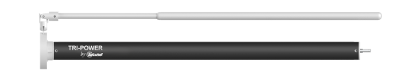
0.8 Nm Motor
Part #: H18-1NM Wand
Description: Tri-Power 0.8 Nm Wand Control Motor

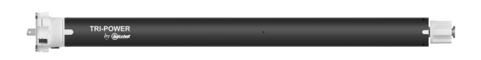
1.1 Nm Motor
Part #: H18-1NM RF
Description: Tri-Power 1.1 Nm RF Control Motor

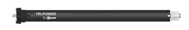
3 Nm Motor
Part #: H18-3NM RF
Description: Tri-Power 3 Nm RF Control Motor
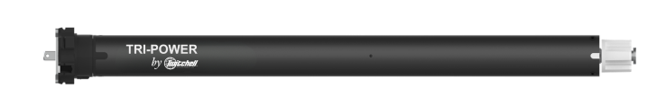
10 Nm Motor
Part #: H18-10NM RF
Description: Tri-Power 10 Nm RF Control Motor
20 Nm Motor
Part #: H18-20NM AC
Description: Tri-Power 20 Nm Exterior Rated RF Control Motor
50 Nm Motor
Part #: H18-50NM AC
Description: Tri-Power 50 Nm Exterior Rated RF Control Motor
Support Videos
Tri-Power Installation Instructions
Tri-Power motors with Smart Power offer the easiest and most flexible method for wiring motorized shades. It is important to follow these installation steps for a successful installation.
Parts/Tools Needed:
- 18/3 or 18/4 wire
- Wire strippers
- 3-conductor splitters (one per motor-part# H18-CONN-3WAY)
- Smart Power motor cables (one per motor-part# H18-USB-6FT or H18-USB-12FT)
- Tri-Power bus tester (part# H18-TESTER)
- Tri-Power motors with Smart Power (part# H18
- Tri-Power Power Hub Kit (part# H18
- Step 1: Locate a good place for the Smart Power Hub
- This should be determined early in construction in order to have power in the correct place
- Must have a 120V outlet for power
- Try to locate the Smart Power Hub towards the middle of the installation to maximize wire length
- Each bus connection is capable of powering up to 20 motors on up to 500’ of 18 AWG wire
- Step 2: Pull 18/3 or 18/4 wire to the window locations from the Smart Power Hub location (18/4 will give you an extra conductor should you find a short later on)
- Wire can be pulled in any configuration including straight line, star pattern, tree pattern, or any combination of those as long as the 500’ accumulative wire length is met
- Use the 3-conductor splitters to branch off in different directions if needed (do not connect wires to splitters yet)
- Make sure to leave 6”-12” of extra wire at motor locations for trimming and stripping wire in the next step
- Step 3: Cut and strip the wire at motor locations
- Using wire strippers, strip back the outer coating of the wire to expose the inner conductors
- Strip back the inner conductors to expose 3/8” to 1/2” of bare wire
- Step 4: Install Splitters to one side of the bus
- Using a small flat head screwdrivers connect one of the bus terminals on the Smart Power Hub to the bus wires by connecting the red wire to the red connection, the black wire to the black connection, and the white wire to the white connection
- Starting at the closest motor location to the Smart Power Hub, connect one side of the splitter only by connecting the red wire to the red connection, the black wire to the black connection, and the white wire to the white connection
- Take care not to leave any exposed conductors on splitters or the Smart Power Hub. If any conductors are exposed, remove wire, trim down, and re-insert so only outer coating is exposed
- Step 5: Power up and test the bus
- Power up the Smart Power Hub by plugging into a power outlet
- Connect the first motor cable to the splitter by connecting the red wire to the red connection, the black wire to the black connection, and the white wire to the white connection
- Plug the motor cable USB-C end into the Bus Tester
- The green and yellow LED on means bus is good
- Other LED lights mean one of the following:
- red and black only – only green LED on
- white wire to red terminal – only green LED on
- white wire to black terminal – only green LED on
- red wire and black wire reversed – only red LED
- Connect the next leg of the bus to the splitter and repeat “step 5” for all motor locations working one motor at a time working away from the Smart Power Hub
- Step 6: Install the shades and plug in motors
- Using the motor cables plug in one motor at a time working from the motor closest to the Smart Power Hub away
- Once a motor is plugged in to the motor cable you will see a blink sequence of blue-yellow-blue yellow. This confirms everything is functioning properly
- If there is no LED blink on the motor check for conductivity using the bus tester
- Step 7: Program remotes and/or keypads to motors
- Add keypads and/or remotes by using the programming instructions included in the keypad or remote boxes
Contact Us